PHYSICAL ASPECTS OF PARANORMAL METAL BENDING
The opportunity to experiment on the paranormal metal-bending abilities of seventeen-year-old Nicholas Williams in his home has been taken on thirteen separate days during 1976. Initial validation tests were carried out according to previously developed methods(1), leaving the maximum amount of time for synchronized chart-recording experiments on signals from two and ultimately three resistive strain gauge sensors.
Synchronicity of signals at strain sensors
As described previously(1), a strain gauge(2) is mounted inside a latchkey and is connected in an electrical bridge circuit, whose off-balance signals are amplified and chart-recorded, usually at a. speed of 4 mm/sec. Two (and ultimately three) such latchkeys are hung by their flexible screened leads, thereby minimizing mechanical and electromagnetic coupling between the specimens. The subject remains seated in a chair remote from latchkeys, and he is usually occupied at building model aircraft. The subject is required to attempt remote bending action on the latchkeys. At certain sessions he has held other metal specimens in his hands, and some of these have bent. The amplifiers are allowed to reach steady conditions and the chart recorders are synchronized. Strain signals are recorded on either or both chart recorders, and occasionally a latchkey bends and ultimately fractures. In a violent bending event the latchkey can be seen to swing to and fro.
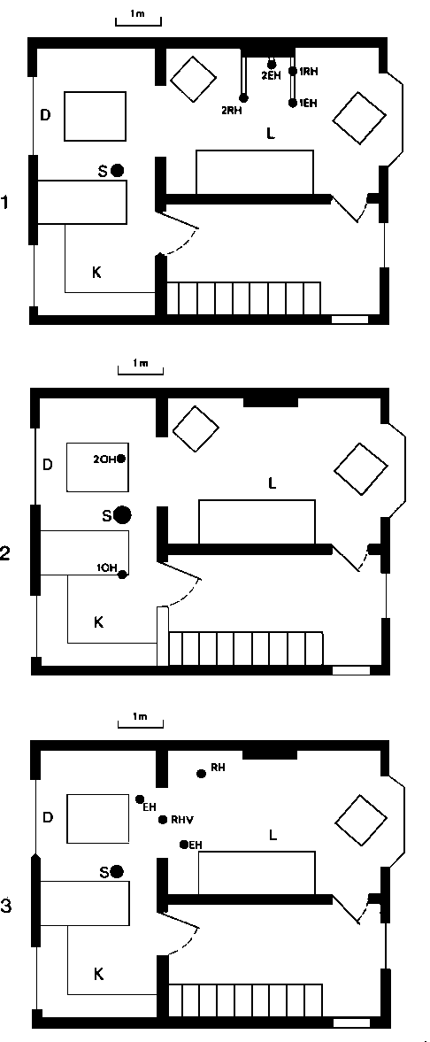
In this type of session the relative positions of specimens and subject were defined as in Figure 1.
Since the sessions can take more than two hours, the visual observation of the subject by the experimenter is not up to the high standards demanded in our previous article (1); but it can be asserted that on many occasions the experimenter was absolutely certain that the subject was not in physical contact either with the sensors or with the electronics at the moment of signal. At other times the experimenter was content to observe the subject from the stairs (Figure 1). The subject’s father and other witnesses were present in the house at various times, but were observed not to have tampered with the sensors; usually they were excluded from the lounge.
Since many synchronous signals were recorded on two, or three, well-separated sensor latchkeys, it would often have been impossible for the subject to bend them manually at precisely the same time, because of their location. The signals can therefore be regarded with confidence as due to paranormal metal-bending pulses produced in the presence of the subject. The bending phenomenon is independent of human touch (the role of which is of some psychological value with many subjects); no attempt has been made to touch the specimens during these recording sessions.
Many ( > 20) hours of operation of the sensing equipment in the absence of a subject have shown it to possess a noise level of the order of 0.5 mV. Complete elimination of electrostatic signals, which are produced for example by rubbing a manmade fibre carpet and then touching the latchkey, is not yet possible; but such signals are now limited to < 12 mV.
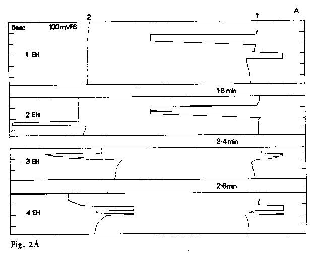
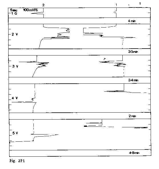
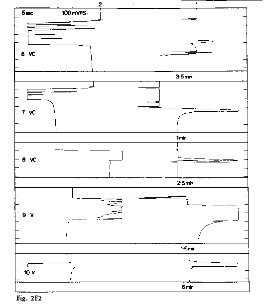
At the first session a single sensor was used, and the two-hour history of the bending of the latchkey has been described previously(1). In this session the subject was seen to bend and twist a number of pieces of cutlery in his hands, and signals appeared on the sensor at the other side of the room during the periods when these bendings were taking place. At the second session (A) two sensors were used, but the problem of keeping the subject stationary was not yet completely solved. At the third session (B) the subject was mostly at an angle of 30 to the line joining the two sensors, and there followed further sessions (C, C1, D) during which the contrast was investigated between the subject being horizontally in line with the two sensors (radial horizontal RH) and his being equidistant from each (equidistant horizontal EH). In session D the effect of screening one of the sensors was Investigated. At the next session (E) the subject was placed horizontally between the two sensors (opposite horizontal OH), and at the next (F), for the first time, the two sensors were moved out of the same horizontal plane, and were placed one above the other. In this session the changes were rung between the three situations: horizontally and radially in line with the subject (RH): vertical (V) and horizontally equidistant (EH) from the subject. In the next session three sensors were arranged with two horizontally in line and the third vertically above the sensor nearest to the subject (RHV). Figure 1 shows these placements, both in themselves and in relation to the house, and Table 1 summarises the data. Figure 2 shows the chart-records of sessions A, F and G; the remainder are available on request, and will be maintained in the archives.
At the final session (H) videotape recordings of a single sensor were made, In synchronism with the chart record. Although no visible bending was revealed in this session, the strain pulses being small, at least there was validation that the subject was not interfering with the sensor manually at the moments of signal.
It is possible to divide the “events” or signals at sessions A-G broadly Into two classes, synchronous (S) and non-synchronous (NS). The contrast appears clearly between the synchronous signals A3, A4 and the adjacent non-synchronous signals A2. Where the signals contain fine structure, which can include both synchronous and non-synchronous pulses, the decision about the classification of the event is made by examining the onsets of the largest pulses in the event. A comparison of Table 1 with Figure 2 will show the justification for each classification. During the entire series of experiments there were 39 (broadly) synchronous events and 32 non-synchronous events. Ten events appeared uniquely (U) on one sensor only. In certain events it appears that one of the synchronous signals is cut off at a small magnitude; these we have termed “suppressed synchronous” (SS).
Discussion of the sensor data: The “surface of action”
The fact that two or even three sensors experience synchronous paranormal force pulses might be interpreted in terms of the following simple physical model.
Let us define a “surface of action” as a geometrical surface over which paranormal bending forces are potentially exerted on solid specimens placed in that surface. When the surface subtends more than one sensor, then synchronous signals are recorded. The fact that unequal synchronous signals are often recorded need not imply that the action varies over the surface. When action in the specimen occurs near to, but not at the embedded sensor, the signal is attenuated. Synchronous signals of unequal magnitude might therefore indicate that the action of the surface was on the latchkey, but not precisely at the sensor.
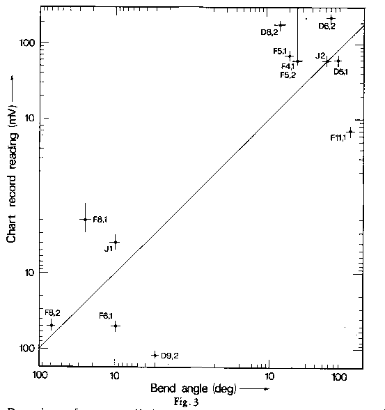
Permanent bends in the latchkeys are recorded as permanent displacements of the chart recorder trace, as for example in Figure 2F(2)8. The magnitudes of these will not be expected to correspond accurately with the visually measured bending angles, since the bends do not take place exactly at the sensor. But there should be some general correspondence both in direction and magnitude, and this is recorded in Figure 3.
Onset or termination of a signal indicate the surface’s arrival at or departure from a sensor specimen. The fine structure exhibited by many signals therefore probably indicates an oscillatory motion of the surface, and the time variations in synchronous signals could indicate flexibility of the surface.
Data from two or three sensors are hardly adequate to obtain detailed knowledge of the configuration or motion of a surface of action. It Is not even clear whether the appropriate model should not be a hypersurface or volume of action. However, a study of the data does yield information about the typical velocities of the surfaces apparently controlled by the unconscious mind of Nicholas Williams. The synchronous signals recorded in experiments with two other subjects show some differences.
A study of Table 1 session F shows that Nicholas Williams eventually learned to produce synchronous events in any of the
configurations RH, EH and V; except in rare instances where action on a unique sensor or on one sensor before the other was required and intended, the subject was always attempting action on both keys simultaneously But it should be remembered that the conscious mind of the subject Is only involved in the events in the most general and oblique way.
In the radial-horizontal RH and the vertical configurations V, as well as In the three-sensor radial-horizontal-vertical configuration RHV, synchronism is the rule rather than the exception
| RH | 9 synchronisms | 3 non-synchronisms |
| V | 6 synchronisms | 3 non-synchronisms |
| RHV | 6 synchronisms | 0 non-synchronisms |
This implies that the most usual configuration for Nicholas’s surface of action is vertical and radial. The synchronicity of signals in the ultimate session with three sensors in a vertical in-line plane bears out the two-sensor data. When the surface is in this configuration the signals at two sensors equidistant from the subject, and in the same horizontal plane (EH), would appear to be non-synchronous, (EH, 13 non-synchronous and unique signals, to 10 synchronous, 6 of them in the successful learning session F). The vertical surface moves between the sensors at a range of speeds between 0.1 and 100 cm/see, these speeds being deduced from the non-synchronous signal spacing. Since synchronous signals seem also to be the rule for the opposite-horizontal configurations (OH: 3 synchronisms, 1 nonsynchronism), it would appear that a vertical radial surface can extend to the rear of the subject. The existence of a vertical principal axis of rotation positioned at the subject is a likely inference.
The production of synchronous signals in the EH configuration is only possible if the surface of action fails to pass through the subject, or if it is bent or curved.
Figure 2F illustrates the beautiful synchronicity of the signals in the “learning” session F with three alternative configurations V, RH and EH. The subject ultimately developed an ability to produce synchronous signals in all three configurations-i.e. to move the surface of action in two directions.
Alternative interpretations of these data might be considered. The most obvious physical model is that of a wavefront being transmitted spherically outwards from the subject, and traveling at a certain speed, affecting the sensor when it reaches it. But if this were so, then synchronous signals at sensors at different distances from the subject would not be the rule, as they are in the radial RH and RHV configurations. Furthermore, non-synchronous signals in the equidistant configuration EH, such as were the rule in the earlier sessions, would only be explicable by a relatively complicated assumption of consecutive pulses, transmitted with different intensity-direction polar diagrams. At times a polar diagram of time-varying width would have to be invoked. Although this cannot be ruled out, it is a much less simple model than that of the moving surface of action. Only when experiments with many sensors have been carried out will we be able to map out the details of the surface. If the folding of a single flexible surface is found to be very complicated, then the possibility of an active volume or hypersurface will have to be considered.
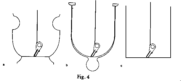
Experiments were carried out in sessions C, D with partial screening (Figure 4) of one sensor whilst both were in the RH configuration. A series of synchronous signals, typical of this configuration, became non-synchronous upon erecting the screen, but the screened sensor signal was not diminished. On the contrary, the partial enclosure of the sensor in a large brass vase (Figure 4a) was associated with a considerable enhancement of the signals, culminating in the first latchkey fracture observed during the sessions. Nevertheless, it should be recorded that the surface of action was disturbed by the presence of partial screening, to an extent apparent from the data in Table 1.
The force at the surface of action
Having proposed the model of a surface of action at which the bending pulses on the sensors in the latchkeys takes place, we must consider what might be the configuration of the forces at the surface. Are they normal to the surface, are they in its plane, or neither?
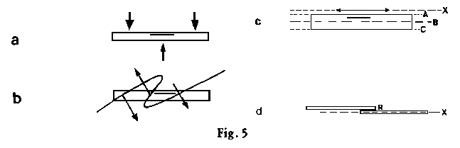
The chart record pulses, in one direction or the other, indicate the lengthening or shortening of the sensor, which is aligned along the latchkey but embedded within it (Figure 5). Bending of the key brings about a lengthening or shortening of the sensor, according to whether it is on the convex or the concave side of the “neutral axis”. The simplest force pattern bringing about such a lengthening is a three-point load (Figure 5a). Therefore, if we were to propose that a force acts normal to the surface, it would be necessary to hypothesise that a fold or kink exists in the surface, so that a three-point load would be applied as in Figure 5b. Thus the hypothesis of uniform normal forces is not the simplest possible, in that one might be able to propose a different force configuration such that no structure in the surface would be necessary.
Such a proposal is that an extension force in the plane of the surface is suffered by the metal. If the surface passes right through the specimen (X-A-B-C in Figure 5c), then signals of opposite sign will be recorded consecutively, as in Figure 2.A.1, sensor 1. But if the surface meets the specimen but fails to reach the neutral plane B. then a signal of single polarity will be recorded, as in Figure 2.A.2, sensor 1.
Unless more than one sensor is mounted in a single specimen, it is impossible to distinguish with certainty between the normal force and the planar extension force by data analysis. It might be claimed that variation in signal with changes in orientations of the specimens with respect to the plane containing them would provide a clue. The approximate specimen orientations were recorded, although some rotation about the vertical suspension wire took place during sessions, but no significant correlation or anti-correlation with normal action could be detected. Extensive curvature in the surfaces would have to be postulated to explain this feature. Visual bendings of the specimens also failed to correlate accurately with proposed orientations of the surface plane. But it will be recalled that the angles of bend showed reasonable correlation with the magnitudes of the corresponding deformation signals, as demonstrated in Figure 3
Although we can find no conclusive evidence from sensor data supporting the planar extension force in preference to the normal force hypothesis, some experiments of a different type are relevant to the choice. In early paranormal bending experiments with specimens composed of two pieces of different metals, bonded together with epoxy resin, it was noticed that the resin fractured on several occasions Since the fabrication of resin bonds requires careful attention to surface conditions, it was decided to expose professionally prepared bonds to paranormal bending action. Strips of aluminium alloy were bonded with various resins by Messrs. Ciba Geigy, and samples were tested to destruction in their laboratory. Other samples were offered to Nicholas Williams and to Willie G. Julie Knowles and Andrew G. Although some were bent without fracture, in most the resin bond suddenly fractured; of these, some showed no bending. The results are summarized in Table 2. They demonstrate that there is a strong shear force acting in the region of the resin bond. Interpretation of this effect on the normal force hypothesis would be complicated. But when the surface of action lies along one of the bonded strips ( Figure 5 d) the planar extension force is of the exact configuration to bring about a fracture of the resin bond.
It will be seen from Table 2 that the forces necessary to fracture the bonds by a straight pull are between 6 and 9.4 KN. (0.225 lb. weight approx. 1N). Such forces could not be produced physically by normal humans, and no signs of the use of machinery were evident in the unwitnessed fractures. But the peel strengths are very much less, and are within the author’s own capability to produce, although possibly not within that of a child. However, when a peel fracture is induced the fractured portion becomes bent, because of the small specimen thicknesses. It would therefore be justifiable to accept as paranormal only those fractures which exhibit no bending.
These results lend some support to the planar extension force hypothesis.
Interpretation of the deformation of thin steps of metal
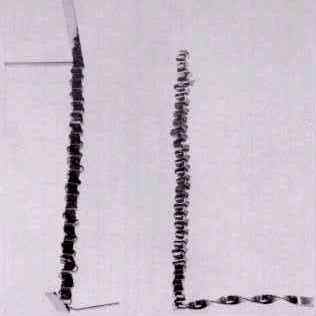
We come now to a series of observations which appear to indicate rotational movement of an active surface. Some identified thin strips of aluminium alloy (6.35 mm x 0.9 mm x 50 cm) were provided to Nicholas Williams, a pair of these were laid across each other and folded once over each other using manual force; they were then left on a table in a small empty and cupboard less third-floor room; we are certain that no one approached or entered the room, or was hidden inside; the experimenter and Nicholas were together, outside the room. Within a few minutes we entered the room and noticed that the folding had continued on its own many times, producing one of the objects shown in Figure 6 The folding process was only found to be repeatable when neither the subject nor the experimenter watched; but rapid movements of the metal strips were heard from outside the room on more than one occasion. Owing to the unavailability of video-recording equipment at that time, it was decided to monitor the process by substituting a permanently magnetized tinned steel strip for one of the aluminium strips; a Newport Instruments fluxgate magnetometer probe was mounted 30 cm from the strips, with the output connected to a chart recorder. The folding and flopping strips produced a magnetic field, from the time-variation of which information about the rate of folding can be obtained. Figure 7 shows chart recordings of magnetic fields made by the folding motion; experiments were also carried out with pairs of magnetized and non-magnetized wires. The correspondence between the number of twists or folds and the number of peaks in the chart-record was sometimes unitary, but on other occasions the fold-and-flop motion of the magnetic strip produced two, three or four pulses to each fold ( Figure 7 (Table 3).
A possible interpretation is that part or all of the surface of action is capable of rotation at several revolutions per second about an axis in its own plane; a pair of specimen wires or metal strips caught in rotations of a sufficiently flexible surface will twist or fold, its maximum rate of twisting being that of the surface. We might suppose that a flexible surface folds so as to wrap itself around the strip.
The action of rotating surfaces may be of importance in the making of paperclip scrunches. When these are formed, unwitnessed, inside an all-glass globe by Andrew G. a hole of diameter >= 2 mm must be left in the globe; in a vacuum-sealed globe no appreciable metal-bending has yet been observed by us. It is possible that screening by the globe of the surface of action prevents its operation inside; but when there is a hole, the axis of rotation of the surface is able to penetrate, so that rotation of part of the surface can take place inside the sphere.
Close to the axis of rotation of an active surface a repetitive shear force could develop. One might speculate that this would be sufficient to bring about metal-softening and violent metal fracture events with localized heating, such as those reported by Franklin(4); metal-softening events have on rare occasions been witnessed by us.
Many unwitnessed events have been brought about by Andrew G in which similar aluminium alloy strip has become twisted about its long axis, as though acted upon by a surface whose axis of rotation is in its own plane The single end of one of the Nicholas Williams folds illustrated in Figure 6 shows this type of behaviour. But it is a more frequent occurrence with Andrew G for a single strip to be curled round in a tight spiral. We stress that the production of spirals is not validated, in that we have not witnessed or instrumented it. However, very similar unvalidated results have been reported independently by Nicholas Williams, Andrew G and Willie G. (unrelated to Andrew G). The production of spirals must involve a persistent bending moment; a clue as to its action was obtained as follows. A number of strips were laid out horizontally for Andrew G; on entry after one minute it was noticed that one of them had become curved sideways into a smooth parabola; the strip still remained flat, without any bending or curling upwards. Such action is very difficult to induce manually; the event was repeated three further times in fifteen minutes. Exact parabolas had previously been obtained with 430 x 6 x 3 mm brass specimens, not only with Andrew G. but also with David Nemeth and with Julie Knowles. Aluminium strip with deep serrations has been used for producing serrated parabolas.
Now it is well-known that the three-point physical loading of a light uniform metal beam produces a cube-law bend. Analysis shows that the square-law curve is the form that would be obtained by the application of a shear moment equal at all points along the specimen. Such a uniform shear, provided that it continued to stay with the metal, would eventually coil it uniformly. It is insufficiently strong to produce a flat spiral, but if it is applied broadside on, then a tight spiral is produced. At a subsequent session a slight parabolic bend was; converted into a tight spiral, showing that with Andrew G the continuous shear can start horizontal and subsequently act out of that plane.
The upper limit to the size of spirals and folds so far produced by Andrew G is about 30 cm, and the lower limit about 2 mm.
The greatest extent of a surface of action we can report is about 10 m; on this occasion a pair of synchronous events occurred on the first and third floors of Nicholas Williams’ house, the sensors being separated by this distance.
Conclusions
Observations of synchronous strain signals from sensors have been interpreted in terms of the physical model of a surface of action in the plane of which forces act upon metal specimens. The surface is supposed to be manoeuvred by the unconscious mind of the subject, and some examples are given of how surfaces may act to produce various forms of bent metal strip. It must be stressed that the operative force fields may actually take forms which are more complicated than surfaces of action; but on the basis of evidence from two or three sensors, the surface is the minimum hypothesis.
No attempt has been made in this report to speculate as to what might be the physical theory from which this model originates. It will not be overlooked that a surface is a boundary between at least two volumes; there is a hint of two separate state vectors 3, or possibly of unconscious control of boundary conditions, or possibly of an energy barrier through which quantum mechanical tunneling might take place.
It is not our intention to propose that all paranormal metal bends are to be interpreted solely by macroscopic surfaces. Structural changes have been reported in certain events, and we hope to report on these in due course.
We are grateful to the Society for financial support of this research.
J.B. Hasted
Department of Physics, Birkbeck College,
University of London
References
(1) J. B. Hasted, “An Experimental Study of the Validity of Metal Bending Phenomena”. Journal of the Society for Psychical Research. Vol. 48 No. 770, 1976. pp. 365383.
(2) Welwyn Strain Measurements type EA-09-BT120 Schlumberger Chart-recorder Type SR204.
(3) H. Everett, J. A. Wheeler and N. Graham, “The Many-Worlds Interpretation of Quantum Mechanics”, ed. DeWitt and Graham, Princeton University Press, Princeton, New Jersey, 1973.
(4) W. Franklin, New Horizons 2, 8 (1975).
| Session | Date (1976) | Designation | Configuration | Synchronization | Range (mV) | Remarks |
| A | 9 Mar | 1 | ~EH | U1 | 0.1 | |
| 2 | ~EH | NS | 0.1 | |||
| 3 | ~EH | S | 0.1 | |||
| 4 | ~EH | S | 0.1 | |||
| B | 18 Mar | 1 | 30° | S | 0.1 | |
| 2 | 30° | NS | 0.1 | |||
| 3 | 30° | NS | 0.1 | |||
| 4 | 30° | S | 0.1 | |||
| 5 | 30° | U2 | 0.1 | |||
| 6 | 30° | S | 0.1 | |||
| 7 | 30° | NS | 0.1 | |||
| 8 | Up | S | 0.1 | |||
| 8a | 30° | U2 | 0.1 | |||
| 9 | 30° | S | 0.1 | |||
| 10 | 30° | S | 0.1 | |||
| 11 | EH | NS | 0.1 | |||
| 12 | 30° | NS | 0.1 | |||
| 13 | RH | S | 0.1 | |||
| 14 | 30° | U2 | 0.1 | |||
| C | 23 Mar | 1 | RH | S | 0.1 | |
| 2 | RH | S | 0.1 | |||
| 3 | RH | S | 0.1 | |||
| 4 | RHS | NS | 0.1 | Screening by kitchen foil | ||
| 5 | RHS | NS | 0.1 | Screening by kitchen foil | ||
| 6 | EH | NS | 0.1 | |||
| 7 | EH | NS | 1 | |||
| 8 | EH | NS | 1 | |||
| 9 | EH | NS | 1 | |||
| 10 | EH | NS | 1 | |||
| 11 | EH | NS | 1 | |||
| C1 | 23 Mar | 1 | EH | S | 0.1 | |
| 2 | EH | S | 0.1 | |||
| 3 | EH | NS | 0.1 | |||
| 4 | RH | S | 0.1 | |||
| 5 | RH | S | 0.1 | |||
| 6 | RH | NS | 0.1 | |||
| D | 9 Apl | 1 | RH | S | 0.1 | |
| 2 | RHS | NS | 0.1 | Glass screen | ||
| 3 | RHS | NS | 0.1 | Glass screen | ||
| 4 | RHS | U1 | 0.1 | Brass screen on key 1 which bent to 70° | ||
| 5 | RHS | NS | l | Steel screen on key 1 which bent to 135° | ||
| 6 | RHS | NS | 1 | Steel screen on key 2, which bent to 60° | ||
| 7 | RH | NS | 1 | Key 1 fractures, key 2 bent at 60° | ||
| 8 | RH | NS | 1 | Key 2 bent to 80° | ||
| 9 | EH | NS | 1 | Key 2 bent to 85° | ||
| 10 | EH | NS | 10 | Key 2 partially fractured | ||
| 11 | EH | U | 10 | Key 2 fractured | ||
| E | 15 Apl | 1 | OH | U1 | 0.1 | Fracture of table spoon with sensor |
| 2 | OHS | NS | 0.1 | Perspex screen on eutectic alloy specimen | ||
| 3 | OHS | NS | 0.1 | ditto | ||
| 4 | OHS | NS | 0.1 | ditto | ||
| 5 | OH | NS | 0.1 | |||
| 6 | 0H | S | 0.1 | |||
| 7 | OH | U1 | 0.1 | |||
| 8 | OH | S | 0.1 | |||
| 9 | OH | S | 0.1 | |||
| 10 | 0H | U1 | 0.1 | Intended key 1 only | ||
| 11 | OH | U2 | 0.1 | Intended key 1 only | ||
| 1 | 23 Apl | 1 | V | S | 0.1 | Unwitnessed alleged paranormal shooting of piece of metal from tube |
| 2 | V | S | 0.1 | |||
| 3 | V | S | 0.1 | |||
| 4 | V | SS | 0.1 | 25° bend on key 1 Failure of chart pen | ||
| 5 | V | SS | 0.1 | 45° bend on key 1, 25° bend on key 2 | ||
| 6 | V | NS | 0.1 | Some misalignment of configuration; 35° bend on key 1, 25° on key 2 | ||
| 7 | V | SS | 0.1 | Some misalignment of configuration | ||
| 8 | V | SS | 0.1 | 10° bend on key 1; 45° on key 2 | ||
| 9 | V | SS | 0.1 | 10° bend on key 1; 45° on key 2 | ||
| 10 | V | S | 0.1 | |||
| 11 | V | NS | 0.1 | Intended delay, 135° bend on key l; 45° on key 2 | ||
| 12 | V | S | 0.1 | Key 1 fractured | ||
| 13 | EH | NS | 0.1 | |||
| 14 | EH | SS | 0.1 | Some misalignment of configuration | ||
| 15 | EH | S | 0.1 | |||
| 16 | V | SS | 0.1 | |||
| 17 | V | NS | 0.1 | |||
| 18 | V | S | 0.1 | |||
| 19 | EH | SS | 0.1 | |||
| 20 | EH | S | 0.1 | |||
| 20a | EH | S | 0.1 | |||
| 21 | V | S | 0.1 | |||
| 22 | EH | S | 0.1 | |||
| 23 | RH | S | 0.1 | |||
| 24 | RH | S | 0.1 | |||
| G | 30 Apl | 1 | RHV | S | 0.1 | |
| 2 | RHV | S | 0.1 | |||
| 3 | RHV | S | 0.1 | |||
| 4 | RHV | S | 0.1 | |||
| 5 | RHV | S | 0.1 | |||
| 6 | RHV | S | 0.1 | |||
| H | 27 May | 1 | Single | 0.1 | All viewed on television monitor | |
| 2 | Single | 0.1 | ||||
| 3 | Single | 0.l | ||||
| 4 | Single | 0.1 | ||||
| 5 | Single | 0.1 |
| Description of resin | Thickness of metal | Strength against tension | Peel strength | Number of unbent fractures | Number of fractures with bend | Number of bends without fractures |
| Standard (twin pack) Araldite AV/HV 100 | 0.914 mm | 6000-7000 N | 12 | 4 | 1 | |
| Redux K6 (phenolic based) | 0.914 mm | 9360 N | 200 N | 2 | 3 | 6 |
| Araldite AV 1523 GB (single component) | 1.651 mm | 9180 N | 369 N | 5 | 1 | 1 |
| High strength Araldite AV 1556 GB (single component) | 1.651 mm | 10,000 N | 144 N | 1 | 5 | |
| ATI powder | 0.914 mm | 11 |
| Designation | Number of Number of folds or twists | Number of peaks in chart record | |
| Fold | M1 1 | 7 | 14 |
| M1 2 | 7 | 21 | |
| M1 3 | 12 | 48 | |
| M1 4 | 23 | 23 | |
| Twisted wire assembly M2A | |||
| 1 | 1 | 1 | |
| 2 | 1 | 1 | |
| 3 | 1 | 1 | |
| 4 | 4 | 4 | |
| 5 | 4 | 8 | |
| Twisted wire assembly | M2C | ||
| 1 | 2 1/2 | 5 | |
| 2 | 4 | 8 | |
| 3 | 2 1/2 | 5 | |
| 4 | 4 | 8 |
Figure 1.
Configurations of sensors and subject (S) in lounge (L), dining room (D) and kitchen (K)
(1) Sensors 1 and 2 arranged in radial horizontal (RH) and equidistant horizontal (EH) configurations. Height of sensors above floor, 110 cm.
This arrangement was used in sessions C, C’, D. In sessions A and B the key positions were similar, but parallel to the wall, and the subject’s position was noted but variable.
(2) Sensors 1 and 2 arranged in opposite horizontal (OH) configuration. Height of sensors above floor, 80 cm. This arrangement was used in session E.
(3) Sensors 1 and 2 arranged in RH, EH and vertical (V) configurations, as used in session F. G. Height of RH and EH keys above floor: 70 cm. Height of V keys (situated at RHV) above floor: 1, 180 cm, 2, 3 cm.
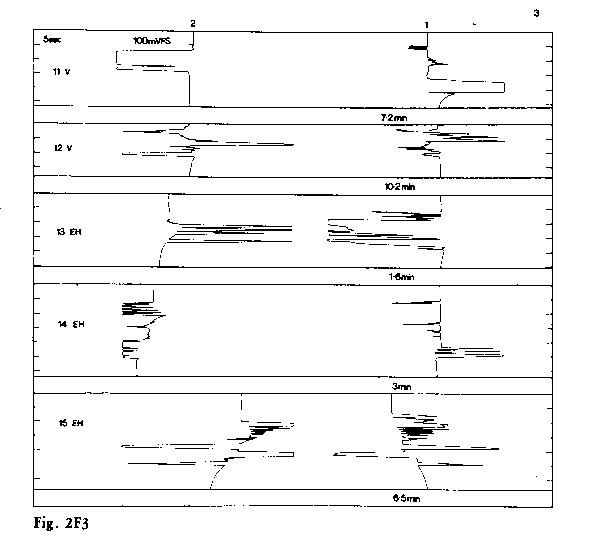
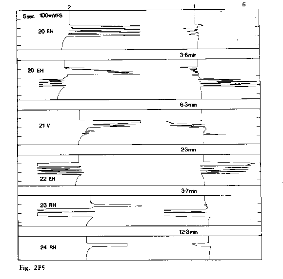
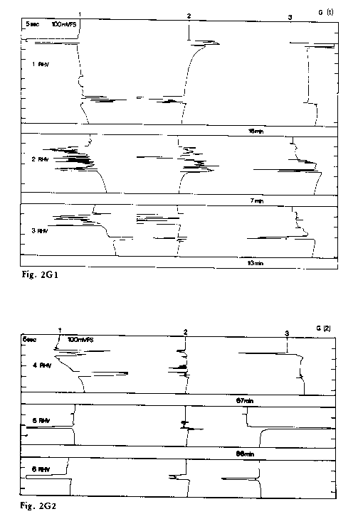
Figs. 2A, F, G.
Figs. 2F1
Figs. 2F2
Figs. 2F3
Figs. 2F4
Figs. 2F5
Figs. 2G1 &2
Record of signals recorded at sessions A, F, G on sensors 1, 2 (and 3 in session G). Sensitivity range shown in millivolts per full scale deflection (FS). 1 mV represents a bending moment of approx. 100 gm weight over 1 cm. The full scale deflection can be recognized by the limitation of signal peaks at their left or right extremity. Time intervals of 5 sec are shown for each event, but the smooth chart recorder traces between each numbered event are replaced by a numerical record of the time interval. Configurations of sensors are shown against each numbered event, the key being given in Table 1.
Bend angle (deg.)
 |
 |
 |
 |
 |
 |
 |
 |
 |
 |
 |
 |
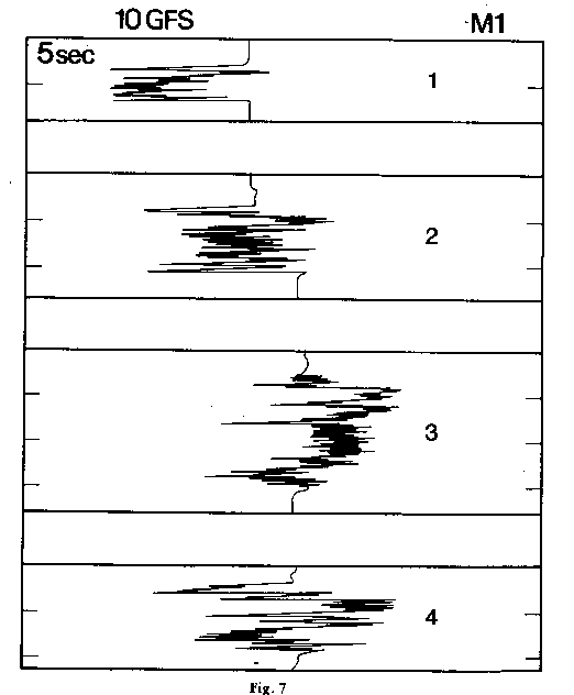 |
Figure 3.
Dependence of permanent displacements of chart recorder trace upon visually measured bending angle, for events indicated in Table 2.
Figure 4
Scale drawings in cross-section of (a) brass; (b) glass and (c.) steel cylindrical screens used in session D. The length of the latchkey is 5 cm.
Figure 5
(a) Side-view of latchkey, with sensor S. Arrows indicate three-point load.
(b) Three-point load which might be produced by forces normal to a kinked surface.
(c) Extension force acts in the directions of the arrows when surface is at A, and until it passes neutral plane B, sensor records an extension pulse. Between B and C, sensor records a contraction pulse.
(d) Extension force acts at X and expands one only of two aluminium strips, thereby causing fracture of epoxy resin R.
Figure 6
Photographs of the first folded aluminium alloy strips produced at the home of Nicholas Williams.
Figure 7
Magnetometer signals obtained during production of folds and wire twists.
Full scale reading, 10 G.
Follow Uri


Latest Articles
Motivational Inspirational Speaker
Motivational, inspirational, empowering compelling 'infotainment' which leaves the audience amazed, mesmerized, motivated, enthusiastic, revitalised and with a much improved positive mental attitude, state of mind & self-belief.